This weeks session focused on myself playing with the moving equipment using Raspberry Pi, Arduino and BBC Micro:Bit Circuit. I took several photos of the practical activity I participated which can be seen below;
Basic Circuits and Equipment compiled together and on their own:
Tech in Motion within class and BBC Micro:bit Coding Site (Before entering my combinations in the coding site);
Tech in Motion within class and BBC Micro:bit Coding Site (After entering my combinations in the coding site);
The thoughts I have on the ‘Make Things Move Session’ is
The link to the Word Document containing the research in relation to unique tech found in ‘Make Things Move’ session can be seen below;
The photos that can be seen below showcase the rough notes I produced in my sketchbook during the first meet up with Uttara Srikanth. Uttara will work opposite me for the final piece of this module. Although there were conversations with Jacob over the last few weeks, it has been decided that myself and Uttara will work together while Jacob will work on his own final piece;
After talking to Tina (Main Tutor) it is recommended that I continue to further continue with the 360 Camera development as well as have a play with the Oculus VR Headset (Look at several Tutorials on how to achieve basic actions and motions for game I’ll create). The suggestion of using ‘Adobe After Effects’ for the 360 Footage/Photo will also be explored throughout the duration of this week (shown through Screenshots and written notes).
24/02/20: At the time this was written I plan to shoot the 360 Footage/Photo on the ground of the chosen location the field although I plan to find (and potentially utilise) a long tripod to place a 360 Camera on. The reason I’ll shoot on the ground is I feel it will create an interesting environment for the player with everything being bigger in proportion rather than trying to recreate the original proportions. I’ll attempt to experiment with the equipment in the bag the camera resides in anyway on Thursday 27th.
The Word Document that can be seen below expands upon a Mood board conveying the imagery and key components that I plan to incorporate into the VR game as well as photos of two to three photos of books I’ll consider incorporating into the VR Game (Research with Added Harvard Referencing). A photo of another Rough Storyboard for the VR Game is also present in the document;
The photos that can be seen below showcase the shoot I performed with the Insta360 camera on the Thursday 27th February 2020. A 360 photo and Video were both taken in the respective locations that can be seen below. The locations that I’ll further upon will be highlighted with a star * opposite the images name;
Location A=
Location B=
Location C=
Location D=
Location E=
Location F=
Location G*=
Location H*=
Location I=
(29/02/20) The Word Document that can be seen below expands on the research I committed to uncovering how to use ‘Unity’ and ‘After Effects’ with added notes and thoughts I have on the how the possible VR Game or Film will be made;
Sketchbook pages below expand on similar notes written within the word document above and scheduling meet ups with the Tutor’s on asking questions about the project I’m working upon;
The sessions topics that were taught during Week 5 consisted of showcasing ‘E-Textiles’ and ‘Wearable Tech’ (Via Raspberry Pi) with many of these pieces involving sewing in LED’s or Circuits within specifically made fabrics to create an interesting interactive piece.
Due to the nature of the class there are no photos of the class performing activities using the technology taught in Week 5 as the fashion design students who were meant to attend and help out in the workshop turned down the offer to participate with the technology and group within the Digital Media course.
The photos that are seen below however are notes I written during the class when the tutor of the module (Emily Godden) went through the various unique ‘E-Textiles’ and ‘Wearable Tech’;
A potential circuit that I’ll consider for the final piece (on my own or in a group) is the ‘Skywriter Touchscreen Circuit’ which could provide a more contemporary edge to the final idea I will further develop for this module;
The thoughts I have initially when observing the ‘E-Textiles’ and ‘Wearable Tech’ displayed in the scheduled session (and in further research I provided for this week) is of raised curiosity in the various pieces that can be created with the combination of Technology and Fabrics. The Wearable Technology appealed to me the most as it best personifies what is expected for this module and also links into another module being taught in the second trimester which will be looked upon more closely.
Despite overlooking the session taught and the research conducted by myself looking into ‘E-Textiles’ and ‘Wearable Tech’, I concluded I wont be providing too much focus on either of these technologies taught in Week 5. The ‘Wearable Tech’ pieces however do link to existing ideas I have made over the past couple of weeks both for this module and the other module (Graphic Design).
The Word Document that can be seen linked below expands on other interesting pieces that fit into the category of ‘E-Textiles’ and ‘Wearable Tech’;
No Blog Post for Week 4 due to absence of Modules Tutor (Tina Burton), the session was cancelled as a result.
The photos that can be seen showcase further development of the Meditation/Mindfulness idea with written notes and mind maps with drawing further fleshing out how the Interactive Application will roughly look like once completed;
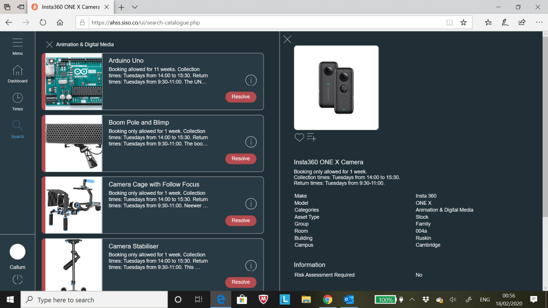
Screenshots and notes that can be seen below demonstrate the experimentation with the ‘Insta360 ONE X’ Camera’ borrowed from the University for the ‘Meditation/Mindfulness’ Interactive application for this module;
AHSS Siso Site 1AHSS Siso Site 2 (Focus on links to PDF’s)Email confirming for use of borrowing Insta 360 Camera and PDF’s accompanying it.
Harvard References to PDF’s needed to operate the ‘Insta360 ONE X’ camera and edit 360 footage which will be captured over the coming week. Images used for Wire frame can also be seen below;
JPEG (produced on Photoshop) that can be seen below showcase the early planning on how the Interactive Application will appear both when the player is wearing the VR Headset as well as demonstrate what can be expected within the game itself which the player interacts with;
*’Anomaly’ is spelt wrong in the JPEG but everything else should be correct.
Photos seen below showcase the Colour Schemes (Colour Wheel) seen in my Rough Wire frame seen above. The iPhone app ‘Adobe Capture’ was used to achieve the Colour Schemes that are presented in this blog;
The screenshots that can be seen below expand on the experimentation I performed on the Insta360 Camera which borrowed during Week 5 till the beginning of Week 6-
Photos from Insta360 Camera App that I used on my iPhone to take the photo/video on 20/02/20;
GoPro VR Player – Adobe Plugin screenshots of untweaked 360 Footage (Footage manipulated using touchscreen via iPad etc.);
Screenshots of Experiment 1 performed on 360 Footage on Premiere Pro;
Screenshots of Experiment 2 performed on 360 Footage within Premiere Pro (Change in GPU Acceleration etc) and GoPro VR Player site;
The second attempt at experimenting with the Insta360 Camera during 21/02/2020 can be seen below with my first attempt at attempting a ‘bullet time’ footage=
Screenshots from tweaks to Video/Photo/Bullet Time on the Insta360 Camera App can be seen as follows:
360 Photo-
360 Video-
360 Bullet Time Unedited-
360 Bullet Time Edited;
Insta360 Camera App Main Menu;
The thoughts I have after experimenting with the Insta360 Camera both on the 20th and 21st February 2020 is amazement of how easy it is to utilise the camera both in taking it from one place to another and how well captured the footage is and the various editing tools that it provides.
After the two days spent on playing about with the Insta360 Camera it has become apparent to that this could provide a firm basis for either this module or the module ‘Interactive Environments’ where this form of technology can be used to its full advantage.
Further experimentation will be considered for this particular brand of tech with tweaks to footage/photos/bullet time shot in Week 5 to thoughts of seriously creating new footage/photos/bullet time pieces.
Harvard Referencing to PDF documents demonstrating the step by step of using a Insta360 Camera can be seen below (as well as other sites pointing out how to manipulate footage on the phone app, premier pro etc);
Further Screenshots can be seen below demonstrating the added Adjustments, Titles and VR Immersion to the 360 Video blog I shot during Week 5;
Despite a lot of cool features added after the edits performed on Premier Pro, the only negative is how long it takes for the VR Video to be exported as it ranges from 2 hours to 6 hours. I had to performed small edits to each edited 360 video MP4 Files exported; the reason for this id when I attempted to add a lot of features and edits to a single 360 video MP4 File it not only crashed the Premier Pro Programme but also the export time would’ve been a full 24 hours to encode.
I’ll strongly consider further working on the Insta360 Camera for the rest of the project due to the many great qualities it has to contribute to an engaging Interactive Application for this module.
The ‘Raspberry Pi’ Circuit Board is a series of small single-board computers developed by the Raspberry Pi Foundation in the United Kingdom. Like the Makey Makey Circuit, this circuit board is used to teach basic computer science in schools and any other facilities linked to the education system.
The photos that can be seen below demonstrate my interaction with the Raspberry Pi equipment during Week 4 with one of the Macs wires used for the ‘Touchscreen Raspberry Pi’;
Instructions given out on how use the Raspberry Pi Ciruit Board.
Touchscreen Homepage.
‘Processing’ Site Page brought up as a potential tech to incorporate with Raspberry Pi.
Main Menu on Touchscreen of Raspberry Pi.
Terminal Page, Coding.
Touchscreen accessing Internet.
‘Terminal’ Page.
Wires from Mac Connected to Raspberry Pi Circuit Board/Touch Screen.
Keyboard used to manouvre game.
The thoughts I had after playing about with the ‘Raspberry Pi’ Circuit Board is how well set up the board is providing many features and functions that lends itself to being incorporated into really interesting interactive pieces not too dissimilar to what was displayed in the previous second years exhibition.
The use of the ‘Processing’ Programme and a Touchscreen proved quite appealing to me as it can lend itself to the ideas I produced over the last four weeks. Further thoughts on ‘Raspberry Pi’ are expanded upon in the ‘Research Word Document’ seen at the end of this blog post.
The ‘Arduino’ Circuit Board consists of both a physical programmable circuit board (referred as a microcontroller) and a piece of software, or IDE (Integrated Development Environment) that runs on a computer/mac, used to write and upload computer code to the physical board.
Experimentation with the ‘Arduino’ set up can also be seen below with an array of photos with Emily (Tutor for this Module) demonstrating how this piece of technology works;
Initial Slide starting demonstration of Arduino Circuit Board.
Arduino Parts Dismantled.
Arduino Compiled together (Distance).
Arduino Circuit Board (Focus on Wires).
Ardduino Circuit compiled together (Close Up).
Emily Testing ‘Touch Sensor’ of Arduino. Part 1.
Emily Testing ‘Touch Sensor’ of Arduino. Part 2.
Page/Site of Coding that can be manipulated that appears when Arduino is plugged into a Mac/Computer.
Wires for Circuit Board.
Black USB connecting Circuit Board to Mac/Computer.
The thoughts that I have after having a play with the mechanics of the ‘Arduino’ Circuit Board is initially of surprise at how the sensor worked as I was unsure what the function of the ‘Arduino’ Circuit was at the beginning of the session. Like ‘Raspberry Pi’, the circuit is easy to set up and is cheap to purchase the equipment.
This will also be considered for the final piece in relation to making the piece more interactive for the individual who will interact with the final piece. Further thoughts on the ‘Arduino’ Circuit Board is expanded upon in the ‘Research Word Document’ seen at the end of this blog post.
Sketchbook Pages containing notes taken during the Week 4’s session can be seen below with a further development in possible ideas with Jacob Barry who, at the time this was written, was considering interest in joining up with me for this module to create a final interactive piece;
The Word Document that is linked below expands on the two unique pieces using the technology of ‘Raspberry Pi’ and ‘Arduino’ with my added thoughts;
The screenshots that can be seen below showcase my experimentation with the Open Processing Programme (Similar to the Process Programme) which allows students/tutors to create visually interesting works via coding which is not too dissimilar to what can be seen in Dreamweaver.
Processing is an Open Source Programming Language/Environment for people who want to create images, animations and interactions. It was originally developed to serve as a software sketchbook and to teach fundamentals of computer programming within a visual context.
Screenshots showcase different coding utilised to create different coloured backgrounds and methods of digitally drawing within the ‘visual’ part of the Open Processing Programme. Screenshots labelled ‘1,2 etc’ to showcase process on how visual sketches were produced.
First Attempt:
1
2
3
4
5
5. Left button triggers visual interactive drawing space.
6. Right button resorts back to coding template.
Second Attempt:
1
2
3
4
5
6. Always Save work otherwise development will be lost.
7. Details to fill in after selecting Save button.
Third Attempt:
1
2
3
4
5
6
7
8
The thoughts I have after experimenting with this programme is it was fun seeing the various potential creative outcomes that can be produced within the programme itself although, like Dreamweaver, the manipulation of coding proved to be a weak point to me due to how much needs to be bared in mind and how easy it is to mess up and not know how to instantly fix the problem. Problems often occur due to small errors of not typing in right symbol or providing the right number of spaces between coding.
Despite the comments I just made I do feel this might be worth looking into again (this will be considered for the other module within this trimester called ‘Graphic Design for the Web’).
The Word Document that can be seen below expand upon further research into the ‘Open Processing’ programme and the games that are created on said programme:
The photos below showcase the notes written in the class during Week 3 and the ‘CAN Conference’ meeting from Week 2 (Sorting out details for registering in the Employment Bureau in the University);
Final Screenshot below showcases the initial ideas development for this module with relation of incorporating the technology that has been taught up to this point;
The photos that can be seen below showcase the notes written in the class during Week 3 and research performed for the ‘Technology Comparison Chart’ through reading articles and watching tutorials;
The Word Document that can be seen linked below showcases the ‘Technology Comparison Chart’ produced in preparation for developing the final interactive application for this module with extra note written seen above in the screenshots related to the technology discussed in the chart;
The photos that can be seen below showcase my attempt at creating a ‘Squishy Circuit’ during the second week of this module:
A ‘Squishy Circuit’ is comprised of a Battery, Two Crocodile Clips, Two Lumps of Play-Doh and a Little light bulb. The idea is to connect all these components together to make the lightbulb glow which can be seen above linked with the bulb connected to both clumps of Play-Doh wired to a battery.
This circuit was taught to showcase how specific materials (Play-Doh) can be used and manipulated into various appealing and creative outcomes as well demonstrate how to create Interactive Pieces in a cost effective fashion.
The thoughts I have after playing about with the Squishy Circuit is although it was interesting witnessing how a Squishy Circuit functions in real time it will not be something that I will factor into the final brainstorm for the piece I’ll make due to the limited uses and presentations the Squishy Circuit Offers.
The next array of photos that can be seen below expand upon the two uses of the ‘Makey Makey’ Circuits;
A Makey Makey Circuit can be used a substitute key board or game controller using the assets of the circuit itself, two or more crocodile clips (clips provide more controls to move objects within computer) and a lead connecting the circuit to a nearby computer or mac.
Photos of myself experimenting with the circuit in question can be seen above with a couple of photos showcasing my hand touching a graphite drawing connected to the crocodile clips and circuit with the light on the circuit turning on once I place a finger on the graphite drawing (touch sensitive) which also turns off once I remove my hand.
This was taught in the class to showcase how easy it is to construct control panel as well as a touch sensitive piece utilising the ‘Makey Makey Circuit’. Unlike the ‘Squishy Circuit’ that can be seen on this blog, I’ll seriously consider incorporating this Circuit as part of the idea mind map I will create for this module in the coming weeks.
The Word Document that can be seen below expands on the research of other interesting ‘Squishy Circuits’ and ‘Makey Makey’ Circuit pieces:
One idea that occurred to me after interacting with a ‘Makey Makey Circuit’ during Week 2 is the idea of utilising the ‘touch sensitive’ aspect of the circuit and incorporate it into a creative art piece in the form of window looking out in the countryside.
There will be two ‘touch sensitive’ hand prints on the left and right side of the of the mock window. When these sensors are touched a digital animation, video footage or photography will appear within the window; when the hands are not touching the sensors the digital display immediately turns with the viewer interacting with piece no longer interacting with the piece
Sketchbook Pages below (Notes taken in the Session taught in Week 2):
Further Sketchbook Pages showcasing planning for ‘Final Story Idea (500 Words)’ and further development on the chosen idea that will incorporated in the final piece for this module:
The link to the Word Document containing the ‘Final Idea Story’ (500 Words) can be seen below:
The photos that can be seen below demonstrate the experimentation in creating a Soil Censor using ‘BBC Microbit’. The ‘Soil Sensor was used to see how much moisture there within a plant pot that was brought into the session during Week 1.
The initial thoughts I has while experimenting with BBC Microbit coding is how intrigued I was initially in how the sensors picked up (successfully) whether there is moisture or not in a plant pot that was handed into class on the day. The many different areas the BBC Micro bit can be incorporated was also really interesting especially after attending the Hack Day the day before the lesson where other activities were laid out on how the Microbit was used from controlling little lights and manipulating text on the Microbit itself which will be considered in the early planning stages for the Interactive piece I will create for this module.
A couple of examples of people creating interesting Interactive Applications using the coding system of BBC Micro:bit can be seen below in the Word Document with added Harvard Referencing:


")


.")


